| 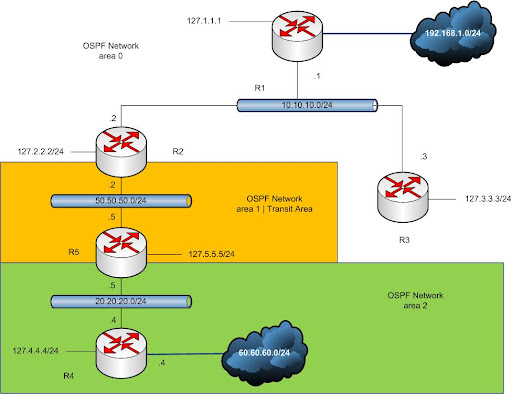
Figure 1 - Network Scenario |
In cases which we cannot have all of our areas directly attached to the backbone area we accomplish this by creating a virtual link from that area through another area which is directly connected to the backbone area, for example in this scenario we have 3 different areas whereas area 2 is not connected directly to the backbone, with certain configurations we would be able to convert area 1 to a transit area so that area 2 would be directly virtually connected to the backbone area zero, routing updates in the transit area are tunneled while data packets are sent over the medium natively without no tunneling overhead, note that ospf transit areas cannot be implemented on any kind of stub areas e.g. totally stub, normal stub, NSSA areas.
Configuring the virtual link should be done on routers which have connectivity to backbone area and the area which is not connected directly to the backbone, in this case R2 is the router connected to the backbone and R5 is connected to area 2 which is not connected to the backbone area.
vyatta@v5# configure
vyatta@v5# set protocols ospf area 1 virtual-link 127.2.2.2
vyatta@v5# commit
vyatta@r2# configure
vyatta@r2# set protocols ospf area 1 virtual-link 127.5.5.5
vyatta@r2# commit
Make sure that after you make the configurations the state of R5 reads area border router and if it doesn’t check for your configurations.
vyatta@v5:~$ show ip ospf
OSPF Routing Process, Router ID: 127.5.5.5
Minimum hold time between consecutive SPFs 1000 millisec(s)
Maximum hold time between consecutive SPFs 10000 millisec(s)
Hold time multiplier is currently 1
SPF algorithm last executed 31m54s ago
SPF timer is inactive
Refresh timer 10 secs
This router is an ABR, ABR type is: Alternative Cisco
Number of external LSA 0. Checksum Sum 0x00000000
Number of opaque AS LSA 0. Checksum Sum 0x00000000
Number of areas attached to this router: 3
Adjacency changes are logged
Execute the ospf neighbor command on r2 and r5 to view the new virtual link that is created between r2 and r5
Both routers believe that they access each other over a virtual interface (VLINK0) additional to the ethernet connections.
vyatta@v5:~$ show ip ospf neighbor
Neighbor ID Pri State Dead Time Address Interface RXmtL RqstL DBsmL
127.2.2.2 1 Full/Backup 34.675s 50.50.50.2 eth0:50.50.50.5 0 0 0
127.4.4.4 1 Full/Backup 35.059s 20.20.20.4 eth1:20.20.20.5 0 0 0
127.2.2.2 1 Full/DROther 36.751s 50.50.50.2 VLINK0
vyatta@r2:~$ show ip ospf neighbor
Neighbor ID Pri State Dead Time Address Interface RXmtL RqstL DBsmL
127.1.1.1 1 Full/DROther 31.386s 10.10.10.1 eth0:10.10.10.2 0 0 0
127.3.3.3 1 Full/DR 34.691s 10.10.10.3 eth0:10.10.10.2 0 0 0
127.5.5.5 1 Full/DR 36.239s 50.50.50.5 eth1:50.50.50.2 0 0 0
127.5.5.5 1 Full/DROther 38.383s 50.50.50.5 VLINK0 0 0 0
Let’s take a look at our OSPF databases:
As you see R1 believes that r2, r3 and r5 are connected to the backbone area and they have advertised router link states in this area, apart from r1, r2 and r3 reside in this area but r5 is connected to this virtually through the transit area we configured on area 1. It also has received some summary type 3 LSA’s form R2 and R5 the area border routers which connect area 2 and 1 to area 0.
vyatta@r3:~$ show ip ospf database
OSPF Router with ID (127.3.3.3)
Router Link States (Area 0.0.0.0)
Link ID ADV Router Age Seq# CkSum Link count
127.1.1.1 127.1.1.1 23 0x8000000c 0xb544 1
127.2.2.2 127.2.2.2 1353 0x8000000f 0x4765 2
127.3.3.3 127.3.3.3 25 0x80000005 0x737f 1
127.5.5.5 127.5.5.5 1358 0x80000002 0x9374 1
Net Link States (Area 0.0.0.0)
Link ID ADV Router Age Seq# CkSum
10.10.10.3 127.3.3.3 20 0x80000003 0xb564
Summary Link States (Area 0.0.0.0)
Link ID ADV Router Age Seq# CkSum Route
20.20.20.0 127.5.5.5 1392 0x80000001 0x1870 20.20.20.0/24
50.50.50.0 127.2.2.2 365 0x80000002 0x191d 50.50.50.0/24
50.50.50.0 127.5.5.5 1392 0x80000001 0xdb52 50.50.50.0/24
60.60.60.0 127.5.5.5 1392 0x80000001 0xd62f 60.60.60.0/24
R4 still remains with the same LSA entries and believes that R5 is its only neighbor, it also has received some summary link states from R5 which is acting as the area border router between area 0 and 2 through the transit area.
vyatta@r4:~$ show ip ospf database
OSPF Router with ID (127.4.4.4)
Router Link States (Area 0.0.0.2)
Link ID ADV Router Age Seq# CkSum Link count
127.4.4.4 127.4.4.4 1625 0x80000007 0xfdde 2
127.5.5.5 127.5.5.5 1471 0x80000004 0x9610 1
Net Link States (Area 0.0.0.2)
Link ID ADV Router Age Seq# CkSum
20.20.20.5 127.5.5.5 1626 0x80000001 0xbeb1
Summary Link States (Area 0.0.0.2)
Link ID ADV Router Age Seq# CkSum Route
10.10.10.0 127.5.5.5 321 0x80000002 0xe3b7 10.10.10.0/24
50.50.50.0 127.5.5.5 1473 0x80000001 0xdb52 50.50.50.0/24
Finally let’s take a look at the ospf database of r2 and the new generated LSA’s:
vyatta@v5:~$ show ip ospf database
OSPF Router with ID (127.5.5.5)
Router Link States (Area 0.0.0.0) ++++++++++++++++++++++++++++++++++++
Link ID ADV Router Age Seq# CkSum Link count
127.1.1.1 127.1.1.1 398 0x8000000c 0xb544 1
127.2.2.2 127.2.2.2 1726 0x8000000f 0x4765 2
127.3.3.3 127.3.3.3 401 0x80000005 0x737f 1
127.5.5.5 127.5.5.5 1730 0x80000002 0x9374 1
Net Link States (Area 0.0.0.0)
Link ID ADV Router Age Seq# CkSum
10.10.10.3 127.3.3.3 396 0x80000003 0xb564
Summary Link States (Area 0.0.0.0)
Link ID ADV Router Age Seq# CkSum Route
20.20.20.0 127.5.5.5 372 0x80000002 0x1671 20.20.20.0/24
50.50.50.0 127.2.2.2 739 0x80000002 0x191d 50.50.50.0/24
50.50.50.0 127.5.5.5 1764 0x80000001 0xdb52 50.50.50.0/24
60.60.60.0 127.5.5.5 1764 0x80000001 0xd62f 60.60.60.0/24
Router Link States (Area 0.0.0.1) ++++++++++++++++++++++++++++++++++++
Link ID ADV Router Age Seq# CkSum Link count
127.2.2.2 127.2.2.2 1731 0x80000007 0x24db 1
127.5.5.5 127.5.5.5 1730 0x80000005 0xaf3d 1
Net Link States (Area 0.0.0.1)
Link ID ADV Router Age Seq# CkSum
50.50.50.5 127.5.5.5 117 0x80000002 0x4ad0
Summary Link States (Area 0.0.0.1)
Link ID ADV Router Age Seq# CkSum Route
10.10.10.0 127.2.2.2 2197 0x80000001 0xc0ee 10.10.10.0/24
20.20.20.0 127.5.5.5 502 0x80000002 0x1671 20.20.20.0/24
60.60.60.0 127.5.5.5 1764 0x80000001 0xd62f 60.60.60.0/24
Router Link States (Area 0.0.0.2) ++++++++++++++++++++++++++++++++++++
Link ID ADV Router Age Seq# CkSum Link count
127.4.4.4 127.4.4.4 119 0x80000008 0xfbdf 2
127.5.5.5 127.5.5.5 1762 0x80000004 0x9610 1
Net Link States (Area 0.0.0.2)
Link ID ADV Router Age Seq# CkSum
20.20.20.5 127.5.5.5 116 0x80000002 0xbcb2
Summary Link States (Area 0.0.0.2)
Link ID ADV Router Age Seq# CkSum Route
10.10.10.0 127.5.5.5 612 0x80000002 0xe3b7 10.10.10.0/24
50.50.50.0 127.5.5.5 1764 0x80000001 0xdb52 50.50.50.0/24
As you see based on the configurations we made r5 is now directly virtually tunneled to the backbone area thus LSA entries for area 0 have been added to our database. This router is now known as an area border router and is injecting summary routes to its attached network into the backbone area. |
|


